


A flange drawing needs to do more than show a flat face and a set of holes. The sealing area must suit the gasket or mating surface, while the bolt holes must align with the mating part and provide the intended fastener clearance. Where a pilot, locating bore or dowel pins position the joint, those features—not the clearance holes—establish the assembly alignment. If those features are dimensioned independently, a flange can be perfectly machinable yet awkward to assemble.
En CNC milled flange design, the useful starting point is the assembled joint: what touches, what locates the parts, and what holds them together. Once those relationships are clear, the drawing can tell a machining supplier which dimensions actually matter.
What must the flange match: the seal, the bolts or both?
Both. The sealing interface determines where the flange contacts a gasket or mating face; the bolt pattern determines how the joint is fastened. The dimensions have to work together because tightening bolts cannot compensate for a misplaced seal, and a well-defined sealing face does not help if the fasteners cannot be installed.
Imagine a flange with a continuous gasket around an opening. Its bolt holes match those on the opposite part, but the gasket contact path sits partly over a recess. The holes may align without resistance, yet the available surface no longer supports the intended seal. Changing the bolt positions alone would not resolve that mismatch.
The same joint can fail at the other interface: a suitable gasket contact area may be present, but the bolt holes sit incorrectly relative to a locating bore or pilot. The mating parts then cannot occupy their intended positions without interference.
Para Piezas fresadas CNC made to customer drawings, these relationships need to be communicated before a supplier can meaningfully review the flange for manufacture. The drawing should show not just individual features, but how the features serve the joint.
Describe the sealing interface before choosing machining details
A machined flange sealing face should be specified around the actual sealing arrangement. A flat gasket, a seal seated in a groove and direct contact between two mating faces may call for different surface geometry. Without knowing which arrangement is intended, the supplier has no sound basis for interpreting an instruction such as “smooth finish.”
Identify the sealing land—the area intended to contact the gasket or opposing face—and show its boundary. This matters especially near openings, recesses and fastening features. A surface can look continuous in an isometric view while a pocket or edge interrupts the very path where the gasket is supposed to sit.
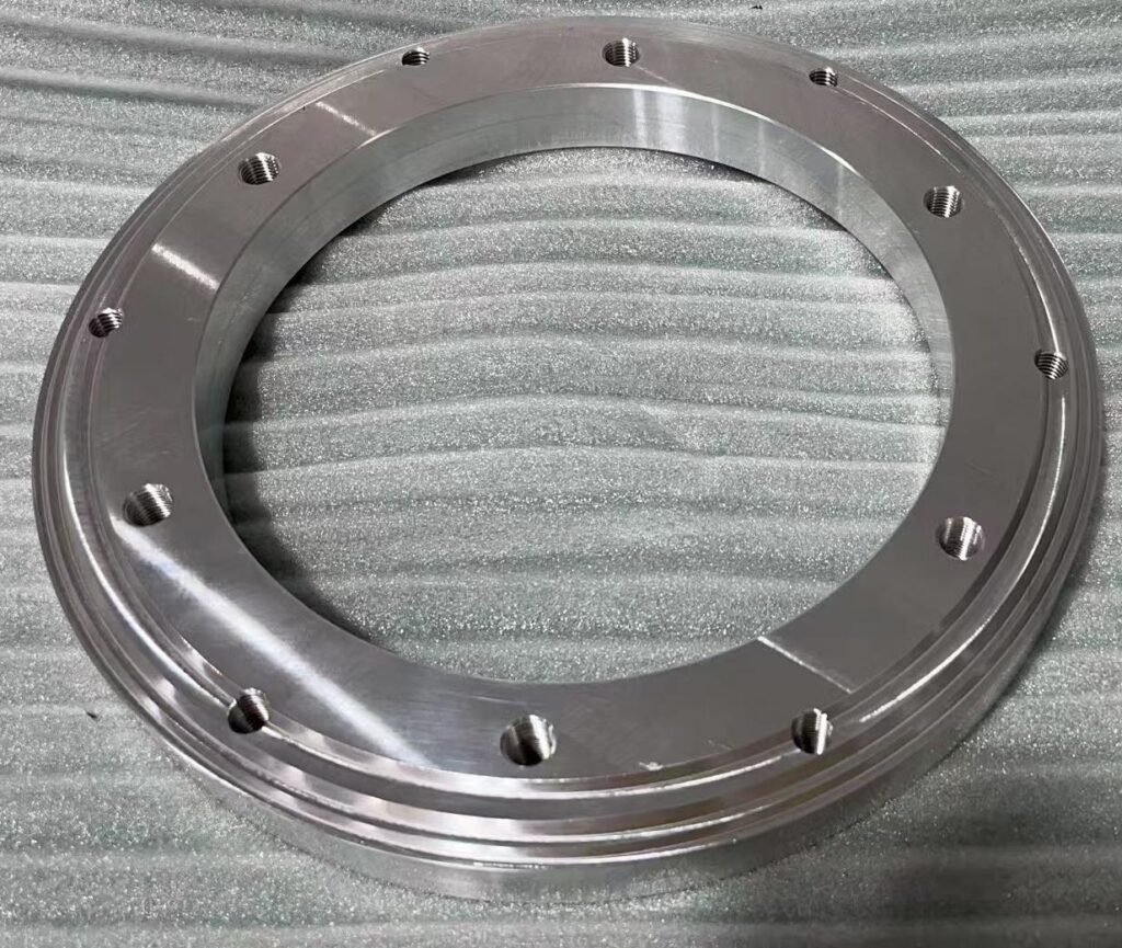
Hypothetical example: A rectangular flange surrounds an opening, with a gasket following the inner perimeter. Its 2D drawing gives the outside size and bolt positions but omits the gasket outline. A small relief cut crosses the proposed contact path. Showing the gasket location or referencing the mating-part drawing allows the engineer and supplier to recognize the conflict before machining.
The necessary flatness, surface texture and relationship to the opposing face should follow the chosen gasket and joint design. Flatness describes variation within a surface; parallelism controls orientation relative to a datum. They address different conditions, so neither should be added as a substitute for understanding the seal.
If the sealing method is not finalized, identify it as an unresolved design decision. Assigning an arbitrary roughness or flatness requirement may create machining work without proving that the completed joint will seal.
Make bolt locations unambiguous
A hole diameter does not tell the full story of flange bolt hole alignment. The drawing also needs to identify the hole pattern, its orientation and the features from which its location is controlled.
For a circular flange, a bolt circle locates the centers of the holes around a common center. The hole count, angular arrangement and relevant location controls must make the pattern clear. Rectangular or irregular flanges may instead use coordinate dimensions or another suitable arrangement of references. There is no universal bolt-circle size that can be selected without the mating-part design.
Locate the pattern from what locates the joint
A datum is a theoretically exact reference used to establish dimensional and geometric relationships. In an assembly, the useful references often come from the mating face, a central pilot, a locating bore or another feature that actually determines how the parts fit. The outside edge is not automatically the right reference just because it is easy to measure.
Consider two hypothetical flanges with the same nominal bolt circle. One part is centered in the assembly by a pilot, but its drawing controls the holes only from an unrelated outer edge. The other part controls its bolt pattern relative to its pilot. Each part might satisfy its own stated dimensions, yet the fasteners may not line up once the pilots engage.
Where hole position is functionally critical, geometric dimensioning and tolerancing (GD&T) can express its permitted variation relative to the chosen datums. The allowance must reflect the fastener clearance and joint design rather than a generic preference for tighter tolerances.
These datum relationships matter during machining and inspection as well. If the sealing face, locating bore and bolt pattern must work together, the supplier needs to understand how those relationships will be established and verified, especially when more than one setup is required.
Orientation deserves the same attention. If the pattern or opening is asymmetric, a defined angular reference, locating feature or identified hole can prevent the part from being assembled in the wrong rotational position.
Check clearance and orientation in the assembled joint
A bolt can pass through its specified hole and still be impossible to tighten. Tool access, washer seating and the direction of fastener insertion depend on the surrounding assembly, not just the flange’s 2D hole pattern.
That distinction is easy to miss when the flange drawing is reviewed on its own. A neighboring wall may obstruct a socket, a raised feature may interfere with a washer, or a fastener may have to approach from a side blocked by the mating component. Hole clearance and tool clearance are different checks.
Where the design uses recessed fastener heads, the counterbore or countersink geometry must also match the selected hardware and leave room for installation. A recess that looks adequate in a section view can still be difficult to reach once the flange is fitted.
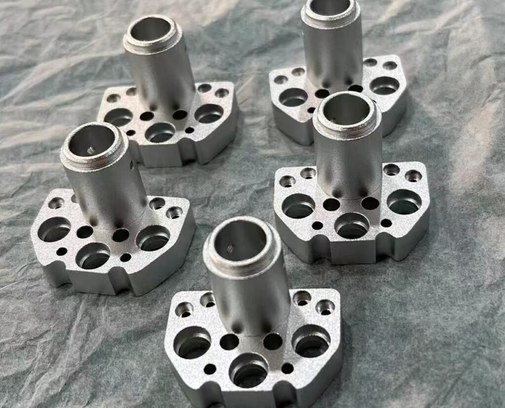
Orientation can introduce a different problem. Imagine a flange with an offset passage and a symmetric set of clearance holes. The bolts may fit in several rotational positions, although only one correctly aligns the passage and gasket with the mating component. The assembly view should identify the intended position rather than leaving it to the installer to infer.
A quick check of the assembled model can reveal these conflicts before a manufacturing drawing is released. Look at how the locating features engage, where the gasket sits, whether fasteners can be inserted and whether the required tools have room to work.
Release a flange drawing that the supplier can review
The best drawing package does not ask the machining supplier to guess what happens after the part leaves the machine. It identifies the sealing contact region, defines the bolt locations from functional references and supplies enough mating-part information to interpret the interface.
Before release, confirm these connected decisions:
- Sealing: Where does the gasket or opposing surface contact the flange, and which requirements apply to that area?
- Location: Which datums control the hole pattern, and how is the required assembly orientation established?
- Assembly: Are the fastener clearance, seating surfaces and tool access consistent with the mating parts?
- Release status: Do the current drawing, CAD model and any mating-interface references agree, and are open decisions clearly identified?
A drawing manufacturability review can identify ambiguous hole callouts, difficult-to-machine features and missing references. It cannot validate a gasket selection or promise a leakage result when the joint design and acceptance requirements have not been supplied. Those decisions remain with the responsible engineering team.
Para CNC milled flange design, confirm the gasket arrangement, mating face and hole-location references first. Then ask for a review of the actual drawing. That order keeps the discussion focused on whether the part can be made and assembled as intended, rather than on specifications chosen without context. When the project moves to quotation, the CNC machining RFQ guide covers the additional drawing, quantity and inspection information worth preparing.
Frequently asked questions
Should the gasket information accompany a flange drawing?
Yes, when it affects the contact area or surface requirements. Send the relevant gasket specification or controlled interface detail, and make sure its revision matches the drawing under review.
Are bolt holes enough to define the flange orientation?
Not if the same hole pattern permits multiple positions while an offset passage, gasket or locating feature requires only one. Add an unambiguous orientation reference.
Can a flange be reviewed without its mating-part details?
Some machining features can be reviewed in isolation. Sealing compatibility, alignment and tool access cannot be assessed fully without the relevant mating-interface information.
A clear flange drawing is one that communicates how the part will fit—not just how it will be cut. Once the sealing and bolt-location requirements are settled, the next useful step is to discuss any machining questions before releasing the part for production.
Have a flange drawing ready for review?
Share the current drawing and available mating-interface or gasket information with CNCRUSH. The team can discuss the machining requirements and clarify any details that need engineering confirmation.
