


CNC turned spacers keep two surfaces at the intended distance in a bolted assembly. Getting that distance right requires more than choosing a tube of the right length: the bolt must pass through as intended, the outside diameter must clear nearby features, and both ends need to seat where the design expects them to.
The most reliable starting point is the assembled joint. Once the actual contact surfaces are clear, the spacer’s length, bore, outside diameter and end-face requirements become much easier to specify on a turning drawing.
What distance must the spacer maintain in the assembly?
Imagine a bracket held away from a mounting plate by a bolt and tubular spacer. The useful distance is measured between the surfaces that actually bear against the spacer’s ends. It may not match the visible gap between the outer faces of the two parts.
A recessed seat, raised boss or washer can change the contact points. If the drawing only shows the overall bracket-to-plate distance, the machinist may have no way to tell which faces establish the spacer length. An assembly section makes that relationship visible without adding unnecessary detail to the individual part drawing.
The spacer’s role also matters. If it sits in the clamping path, tightening the fastener places it under compression. Its material, wall section and bearing area therefore need to suit the specified preload and any relevant service load. Excessive deformation can change the intended separation or affect how the joint remains in contact.
A sleeve used only to provide bolt clearance has a different function and should not automatically be treated as a load-carrying member. Establish which components carry the clamp load before finalising the spacer dimensions.
Start with length and the assembled stack
Spacer length should follow the assembled arrangement, not an isolated gap measurement. The stack is the sequence of components along the bolt axis; its actual contact surfaces determine how much space the spacer must occupy.
Hypothetical example: A bracket rests on one end of a spacer while the other end contacts a housing. A washer beneath the bolt head changes the bolt’s grip arrangement but does not necessarily change the required spacer length. Move that washer between the spacer and housing, however, and the contact stack changes. The length now needs another look.
This is useful context when discussing a custom part with a turning supplier. For drawing-based CNC esztergált alkatrészek, the assembly view explains which dimensions are functional, rather than leaving the supplier to infer their purpose from a cylinder on a drawing.
What happens when the adjoining parts vary?
A nominal gap describes only one condition. The spacer and mating components each have permitted dimensional variation, which together forms a tolerance stack-up. At one combination of allowed limits, the spacer may seat as intended; at another, it may leave an unwanted gap or prevent a mating face from reaching its required position.
The useful drawing question: What must remain in contact, and what separation is acceptable, across the permitted variation of the assembled parts?
Answer that before applying a length tolerance. Bolt grip, thread engagement and the possibility of bottoming out also need checking against the complete assembly; a correct spacer length cannot rescue an unsuitable fastener arrangement.
Check inside and outside diameters against nearby parts
A inside diameter must suit the part of the bolt that travels through the spacer. A bore that is unnecessarily close-fitting may make assembly difficult when the holes in the adjoining parts vary in position. Excessive clearance can also be a problem if the design expects the spacer to help locate the bolt or mating parts.
Decide whether the bore is there simply for fastener passage or whether it has a locating function. The correct spacer bolt clearance comes from that relationship, not from an assumed universal bore size.
A outside diameter must clear neighboring geometry. Together with the bore diameter and any edge chamfer, it defines the available annular bearing land at the ends. Check ribs, counterbores, bosses, recesses and any nearby moving parts. A sleeve may fit over the bolt perfectly and still fail to seat because its outer edge strikes a raised feature.
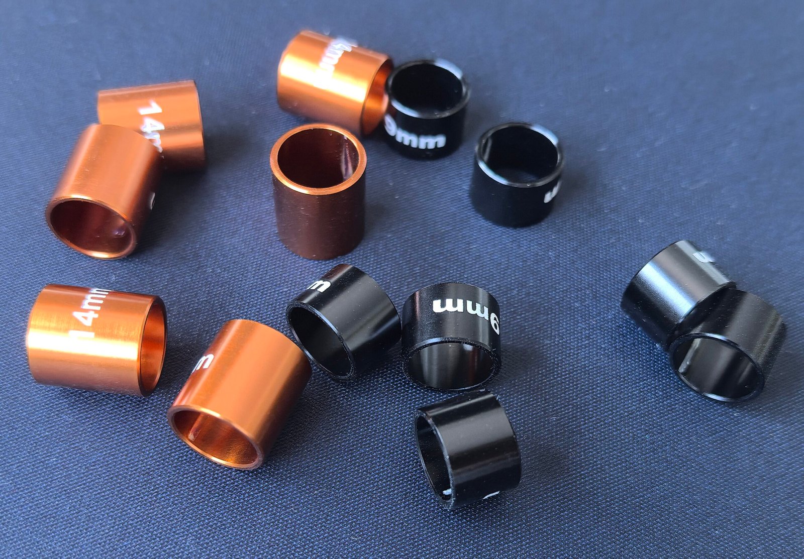
Hypothetical example: A tubular spacer clears the bolt and the bracket hole, but a small boss surrounds the threaded opening in the housing. If the sleeve lands partly on that boss, its end face may never reach the intended seating plane. Changing only the bore would not solve the problem; the outer envelope and mating geometry need review.
Also consider the width of the flat contact area around each hole. An outside diameter that overlaps a fillet or recess can create edge contact instead of full seating. Larger is not automatically safer; the appropriate diameter depends on the joint’s available clamping surfaces and the design requirements.
Why do the two end faces matter?
A spacer can have the right length and diameters yet sit incorrectly if its ends do not meet the mating surfaces as intended. Uneven seating can change the effective separation or introduce tilt when the joint is tightened. For a component whose purpose is to hold a controlled distance, those end-face relationships are not a cosmetic detail.
Three geometric controls may be relevant, depending on how the spacer seats. Flatness controls the form of each bearing face; parallelism controls an end face relative to a specified datum plane, such as the opposite end face when it is designated as the datum; and perpendicularity controls an end face relative to a specified datum axis or plane.
These controls are not interchangeable. The drawing should identify only the geometric relationships that affect assembly, with tolerances based on the joint’s functional requirements rather than simply because the part is CNC turned.
Small edge features can matter too. A burr may hold one end away from its intended seat, while an edge break or chamfer that is unsuitable for the mating geometry can reduce the available contact area. These details should be considered against the actual adjoining surfaces, not copied from a generic spacer drawing.
Where alignment is important, define the contact faces and relevant datums clearly. A strict length dimension by itself says little about whether the spacer will sit squarely once installed.
Prepare the spacer drawing for a turning review
By this stage, the drawing should describe a specific interface rather than simply a hollow cylinder. Show the finished length, inside and outside diameters, and any end-face or edge requirements that affect assembly. Use tolerances justified by the fit and identify the datums or mating references behind critical requirements.
A section view is particularly helpful when the spacer sits against recessed faces or shares the bolt stack with washers. It lets the turning reviewer see why one surface matters and another may be less critical. It can also expose a conflict between the intended spacer length and the bolt or washer arrangement before the parts are made.
For a practical drawing review, the essential information is compact: the current spacer drawing, a relevant assembly view, the bolt and washer arrangement, and any unresolved fit or contact questions. If the spacer carries clamp load, include the applicable preload or design-load requirement, or identify the controlled assembly specification that defines it. Material and other specifications should come from the approved part requirements rather than assumptions about what a spacer usually needs.
For a broader overview of the information needed when requesting a machining quote, see our guide to CNC machining RFQ requirements.
Confirm the assembled stack first, then finalise the machined spacer dimensions and end-face controls. That sequence gives both engineering and purchasing teams a clearer basis for reviewing the custom turning requirement.
Frequently asked questions
Is a turned spacer the same as a bushing?
Not necessarily. A spacer establishes separation between components, while a bushing is often designed around a shaft or pin interface. Similar shapes do not make their functional requirements interchangeable.
Should spacer length be chosen before the bolt?
Establish the required separation and contact stack first, then check the bolt’s grip, clearance and engagement against that arrangement. If the fastener is already fixed, review the spacer and bolt together.
What mating information helps review spacer dimensions?
An assembly section showing the contact faces, bolt and washers, nearby interference features and relevant datums is especially useful. The spacer drawing should still state its own controlled dimensions.
Ready to review a custom turned spacer?
Share your current drawing and the assembly view showing where the spacer seats. CNCRUSH can review the supplied part requirements and discuss any dimensions or interface details that need clarification before quotation.
