


UN counterbore is the right choice when a screw head needs a flat-bottomed recess. A countersink is intended for a flat-head screw with a tapered underside. Both can keep fasteners from projecting above a machined surface, but they support different head shapes and require different drawing dimensions.
Choosing between a counterbore and a countersink is only part of specifying a CNC-milled part. The selected screw must seat correctly, enough material must remain around and beneath the recess, and the drawing must define the feature clearly enough for machining and inspection. Resolving these details before release helps prevent a part that meets the nominal hole dimensions but does not assemble as intended.
Does the screw head need a flat recess or a tapered seat?
The difference becomes clear when looking at the underside of the screw head. A socket head cap screw, for example, has a flat bearing surface beneath its cylindrical head. A counterbore provides a recessed, flat seating face for that type of fastener.
A flat-head screw works differently. Its tapered underside is designed to bear against a matching conical surface. That is why it belongs in a countersink rather than a cylindrical pocket.
The difference that matters
Counterbore: A cylindrical recess with a flat bottom, typically used to accommodate a screw head with a flat underside.
Countersink: A conical recess designed to match the tapered underside of a countersunk screw.
Counterbore vs Countersink: Cross-Section Comparison
|
Counterbore Cylindrical recess · flat-bottom seat
The cylindrical head sits on a flat floor. The smaller shank hole continues below the recess. Key drawing details: counterbore diameter and recess depth. |
|||||||||
|
Countersink Conical recess · tapered seat The tapered screw head follows the conical seat and transitions into the smaller shank hole. Key drawing details: countersink major diameter and included angle. |
Schematic cross-sections only · not to scale · confirm geometry against the selected fastener specification.
Neither feature should be selected simply because the finished screw head needs to sit below the surface. The required contact between the head and its seating face is what determines the correct geometry.
This also explains why changing the fastener late in a project can affect the machined part. Replacing a socket head screw with a flat-head screw may require a different recess, even when the thread size and nominal hole position remain unchanged.
When does a counterbore make sense?
Counterbores are useful when the assembly calls for a cylindrical-head fastener but cannot accommodate a protruding head. A mounting plate beneath a sliding cover is one possible example. Recessing the screw head can provide the necessary clearance without changing the intended flat seating arrangement.
The important dimensions are the counterbore diameter and depth. The diameter must provide clearance for the selected head and account for any relevant installation requirements. The depth determines where the head sits relative to the outer surface.
A deeper pocket is not automatically better. Removing additional material reduces the section beneath the screw head, which may be significant in a thin plate or near an edge. A very narrow recess can also leave insufficient room for a socket or other tightening tool.
These details are worth discussing when specifying custom Pièces fraisées CNC, particularly when mounting holes sit close to pockets, walls or other functional features.
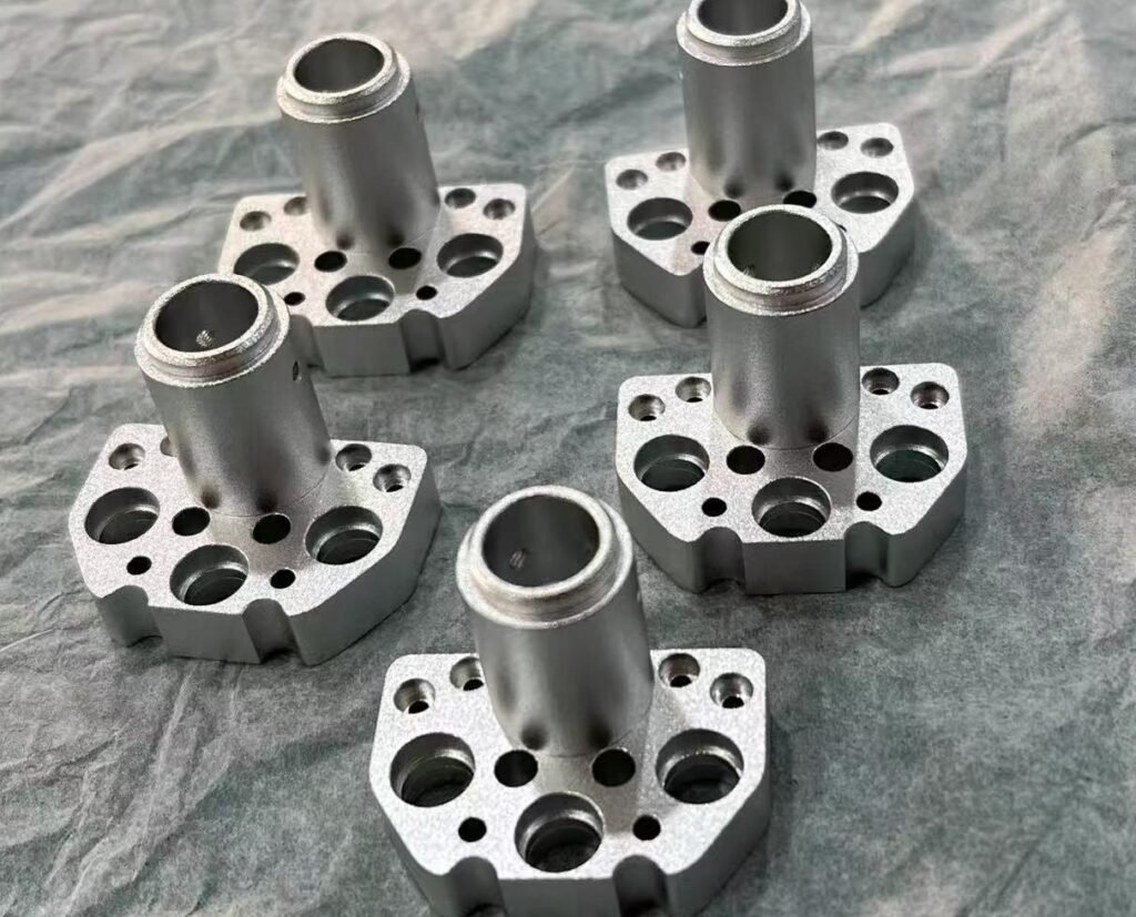
Consider a hypothetical mounting bracket with a socket head screw positioned near an internal corner. The head may fit inside the proposed counterbore, yet the assembly tool may still be unable to reach it. That problem is easier to resolve in the design than after the brackets have been machined.
For recessed fasteners, the correct pocket is one that accommodates the selected hardware, preserves the required seating surface and leaves enough material for the joint’s intended function.
When is a countersink the better fit?
A countersink becomes the better option when the design uses a flat-head screw and needs its head to sit at a controlled height relative to the surface. This is common in panel-type assemblies where protruding fasteners would interfere with a cover, adjacent component or moving part.
Imagine a removable panel secured to a milled enclosure. The panel needs a relatively unobstructed outer face, so the designer selects countersunk screws. The conical recess allows the specified head to sit in the panel, provided the angle and opening diameter match the hardware.
Le countersink angle is especially important. Flat-head screws do not all share one universal head angle. A countersink made to the wrong angle may contact the screw unevenly, even if the opening appears wide enough.
Head position matters as well. A countersink that is too shallow or too small may leave the head standing proud. An oversized recess can leave the head too far below the intended surface and change its seating contact.
The drawing should therefore identify the selected fastener and its compatible seat geometry. Do not substitute a general edge chamfer for a functional countersink. A chamfer intended to remove sharp edges does not necessarily provide the controlled bearing surface needed beneath a screw head.
A spotface is worth distinguishing as well. It is a shallow, flat-bottomed machined area around a hole, used to provide a clean, level bearing surface when the surrounding face is uneven or unsuitable for direct seating. Although its geometry resembles a shallow counterbore, its purpose is usually to create a bearing surface rather than to house the full screw head. It is not a substitute for a countersink when the selected fastener requires a conical seat.
There is also a material trade-off. A large countersink in a thin section may remove more of the surrounding material than the design can accommodate. In that situation, reconsider the fastener arrangement rather than assuming a flush head is worth the loss of material.
What must the hole callout communicate?
A machining drawing should make the recess recognizable without requiring the supplier to guess which screw will be installed. That means distinguishing the smaller hole from the larger seating feature and identifying the dimensions that control each one.
The smaller hole should be defined by both its function and its depth. A clearance hole allows the screw shank to pass without engaging threads, while a tapped hole provides thread engagement. For a clearance hole, state whether it passes through the part. For a tapped hole, specify the thread designation and, where applicable, the usable thread depth and whether the hole is blind or through.
Counterbore dimensions
For a counterbore, identify the smaller hole diameter, the larger counterbore diameter and the recess depth measured from a defined surface. State whether the smaller hole passes through the part or stops at a specified depth.
A machinist should not need to infer pocket depth from the screw head or decide which side of the plate receives the counterbore. Where the feature is not obvious in the main view, a section view can make the relationship much easier to understand.
Countersink dimensions
A countersink normally needs the smaller hole diameter, the major diameter of the conical opening and its included angle. If screw-head flushness is important, the drawing should also communicate the required head position and how that requirement is to be assessed.
The fastener reference is just as important as the geometric callout. A screw size without its head type or applicable specification may leave uncertainty about the seating geometry.
Hypothetical drawing issue: A mounting plate shows two concentric circles around each screw location but gives no recess depth, angle or fastener designation. The outer circle could represent a counterbore, countersink or another feature. Adding the appropriate callout and hardware reference resolves the question before machining begins.
For repeated mounting holes, the drawing must also communicate their number and positions. Where alignment is functionally important, relate the positions to the appropriate datum references and specify suitable tolerances. A perfectly machined recess is of little use if its hole is in the wrong place for the mating part.
Check the fastening stack before releasing the drawing
A counterbore or countersink may be dimensionally correct and still create problems once the assembly comes together. The final review should consider the full fastening stack: the part with the recess, the components being clamped and the threaded feature or nut receiving the screw.
Think about what happens when the screw is tightened. Does the head reach its intended seating face? Is the screw long enough to provide the required engagement without bottoming out in a blind threaded hole? Can the installer reach the drive after surrounding components are fitted?
These are assembly questions, not merely machining questions. The part may meet every isolated hole dimension while the selected screw or installation sequence remains unsuitable.
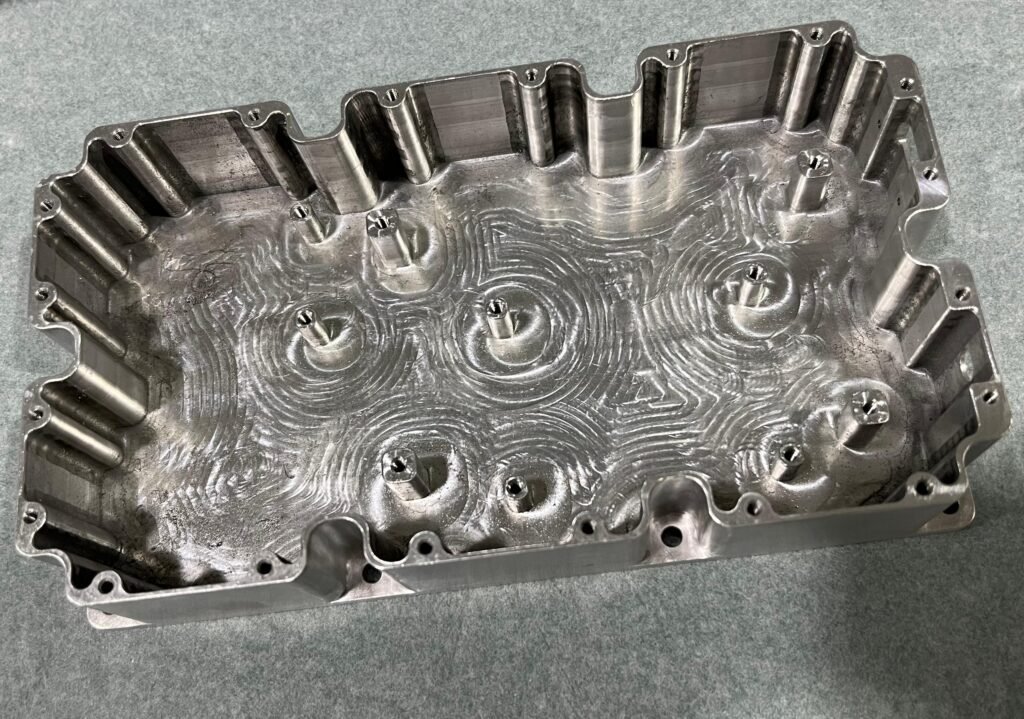
Machining access should also be considered separately from screw access. A recess may be straightforward to use during assembly but difficult to machine if it sits close to an internal wall, deep inside a pocket or on a face that requires another setup. Tool reach, available clearance and the intended inspection method should be reviewed before the drawing is released. These factors can affect the practical machining approach without changing the required fastener geometry.
A further distinction is between fastening and locating. Screws normally provide clamping force, while features such as locating pins may establish a repeatable position between mating parts. A recessed screw head does not automatically make its hole a precision locating feature.
Before releasing the drawing, compare the recess with the actual selected screw and the mating assembly. Confirm the seating geometry, the material remaining beneath the recess and the access needed for installation. Any unresolved requirement should be identified rather than left for the machine shop to interpret.
Frequently asked questions
Can a counterbore and a countersink use the same screw?
Not normally without changing the intended seating arrangement. Cylindrical-head and flat-head screws have different bearing surfaces. If the screw type changes, check whether the recess and fastening stack also need to change.
Does a countersink angle always have one standard value?
No. Different fastener specifications can use different head angles. The drawing should specify an angle compatible with the selected screw rather than rely on an assumed default.
What if the recess leaves too little material?
Review the local part thickness, recess dimensions and fastening arrangement before machining. A different screw head, revised hole position or additional local material may be considered, but the design owner must assess the suitability of any change.
Choosing between a counterbore and a countersink starts with the fastener itself. Select the head geometry, determine how it needs to sit in the assembly, and define the matching recess on the engineering drawing.
Need to review recessed fastener features?
Share your current milling drawing, selected screw specification and any concerns about head clearance, recess depth or assembly access. CNCRUSH can discuss the drawing requirements for your custom milled parts and identify points that may need clarification before manufacturing.
